Connection - Alphatech (en)


Main menu:
Connection
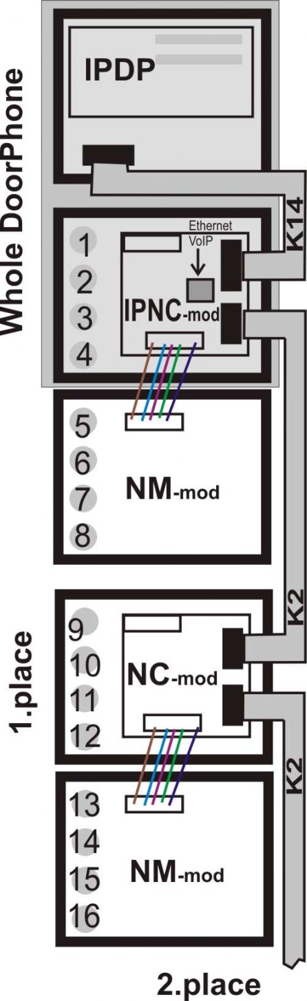
The IPDP structural elements are the basic modules with color camera IPDP or without camera IPDP-00 and extending button modules IPNC1 with one button, IPNC2-mod with two buttons, IPNC4-mod, NC and NM-mod4 with four buttons.
The “14 pin black conector” serves the connection of extending modules by means of flat cable.
The “USB” serves the connection internal color camera
For IPDP is necessary used the AC voltage of min. 10Vst - max. 15Vst or DC voltage of min. 12Vss to max. 18Vss must be energized to “12V” terminal. This source loading depends on number of modules, since it simultaneously serves feeding of lighting through visiting cards – at max. number of connected modules the demand will not exceed 300mA. This source can be also used for feeding of lock(s), and then it is necessary to consider the electrical lock demand. In practice the alternating feeder 12V/1A mostly meets these demands.
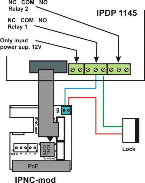
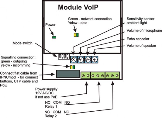
IPDP receives power through the PoE (Power over Ethernet) technology. No additional cabling is necessary. If your Ethernet is not equipped with the PoE technology it is possible to use a PoE adaptor (IEEE802.3af). If you are using electric lock for opening door, so you must use for activate electrical lock power supply 12V (only in circuit with Relay contact) or use lowpower lock (max. curent = 300mA) and for power electrical lock use connector on IPNC-mod "12V" and if doorphone is powered by PoE here is 12V/350mA for lock. Pict.
The connection of relay contact terminals is shown on . The “NO” designation means an idle-disconnected contact, “COM” means a pin contact (middle) and “NC” means an idle-connected contact. The contacts of both switches are galvanically isolated each other and from other guard circuits. The variants of connection are shown on picture.
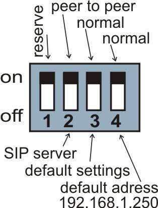
DIP switch setting basic operation and default setting. See on picture
1-reserve
2-switch mode P2P / SIP server
3-basic setting – erase all values to the service setting except memoirs numbers
4-adjust starting IP address 192.168.1.250
DIP switch settings
All changes is execute always after restart of IPDP .
DIP switch 3 and 4 after starting VoIP module you must switch back to position "on" else newly setting parameters or new IP address after reboot IP module overwrite back to basic value.
Connection IPNCmod / NCmod
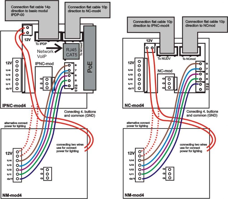
This module is supplied in three designs. The IPNCx-mod module (picture) has four buttons and includes the electronics to be connected to the basic module. The NC-mod4 module has four buttons and includes the electronics to be connected to the IPNCx-mod or to previous NC-mod4 module. This module is only connected by flat cable – buttons and lighting through is already interconnected. The terminals for connection of other four buttons and current supply of lighting are further placed on module (on following NM-mod4). The NM module is always connected to previous IPNCx-mod or NC.
The flat cable connection is facilitated by connector locks, preventing from rotation, but to keep the connection routing is imperative. “To IP DoorPhone” is always the routing to the basic module. “To NCmod” is routing to the row end (on last NC-mod).
On board NC-mod/IPNC-mod is connector 12V. Here’s source DC 12V (on board is marked polarity), which it is possible use for lighting in additional modulus, further it is possible 12V max 350mA use for open lowpower electrical lock. On this connector 12V is 12V at supply from external power supply and too while using supply by PoE.